Introduction
REMEMBER to record (like, take photos of) screws you removed. Some are fine metal thread type and others are coarse self-tap for plastic. Do not mix them!
-
-
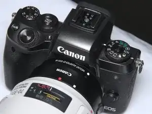
Canon EOS M5
-
Remove the strap, Or, it WILL cause mess during the teardown/repair. Remove it unless you are as SKILLFUL (lazy) as I am.
-
-
-
FIRST remove battery and SD card.
-
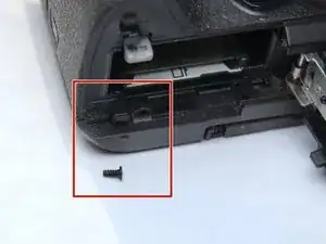
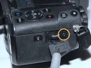
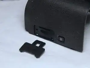
remove 1 self-tap screw
-
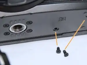
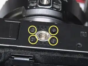
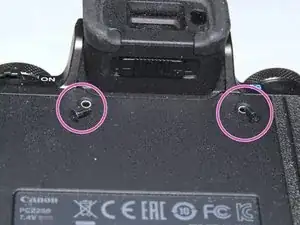
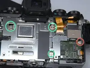
remove 6 screws
-
These 2
-
And these 4
-
-
-
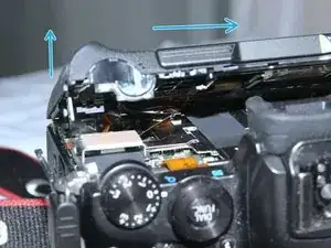
Gently, lift (towards back) and slide the back cover towards left (THE LEFT when you holding the camera)
-
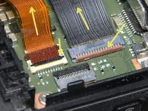
Disconnect 2 FPC.
-
-
-
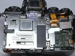
Remove 3 screws near the EVF. REMEMBER lengths and hole positions. The center one is longer. The left holes.
-
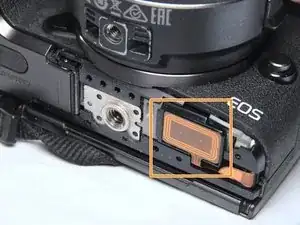
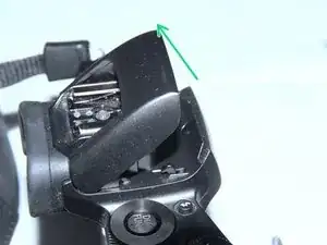
Pop the speedlight (flash)
-
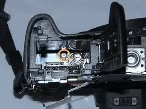
Remove the screw covered by the speedlight.
-
-
-
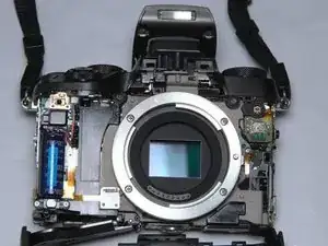
Please keep body cap on as possible, for shielding again dust.
-
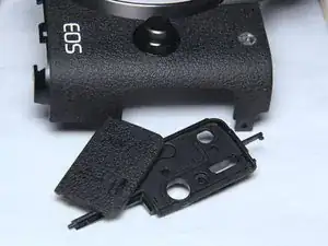
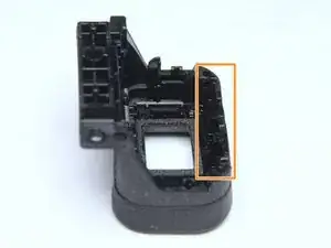
Front cover comes off with 2 small parts. Don't loose them.
-
-
-
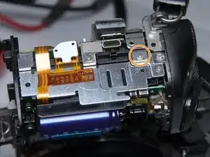
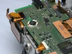
The capacitor
-
To avoid electric shock and damage, DISCHARGE IT with a 2kohm~10kohm resistor for more than 15 seconds, ASAP!!!
-
-
-
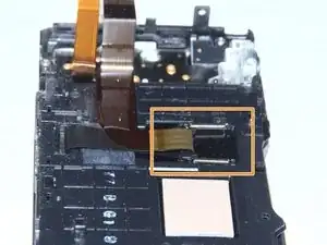
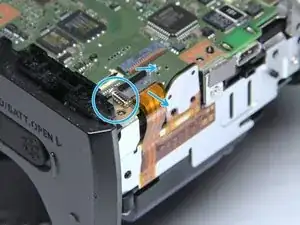
Detach FPC.
-
Be gentle enough We do NOT remove top case. Because it's kind of messy with some adhesive...
-
-
-
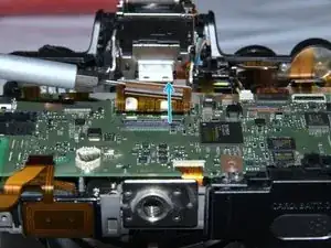
When the top case is loosen. remove the metal frame.
-
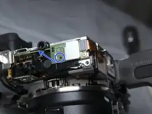
Or you can remove this BlueTooth board if not being lazy.
-
-
-
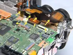
IF you can count to 5:
-
PCB top left, detach 2 FPC. 1 ZIF, 1 non-ZIF
-
PCB top right, detach 4 FPC and 1 cable connector
-
PCB top center. detach sensor cable.
-
-
-
Ladies and gentlemen, the mother board
-
Digic and RAM
-
RTC battery
-
Some Flash
-
SD socket
-
Some power supply
-


10 comments
Thank You!!
Is there a way to remove and replace the rubber eye cup without disassembly?
I'm not quite sure, I sticks very tight. possibly glued or even moulded together
Terrance -
Does anybody know where to buy screws shown on step 6 or what size they are? One of those fell out of my camera.
As I measured, it smells like M1.7x0.35*4.5mm CM head. you can get away with M1.6x0.35x4.5 as they share same pitch 0.35mm, length 4.0 should also be ok.
Terrance -