Introduction
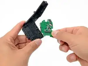
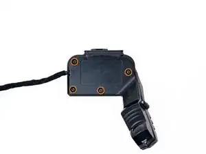
No button response or viewfinder image in your Zeal Optics iON goggles? Use this guide to replace a faulty button board, which also connects to the viewfinder lens assembly.
-
-
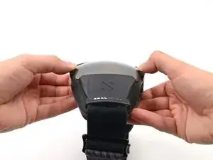
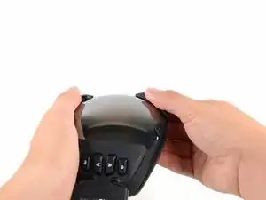
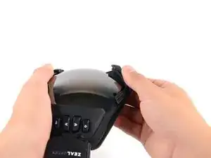
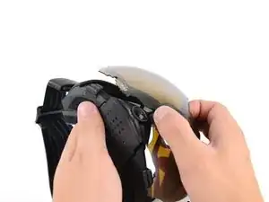
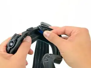
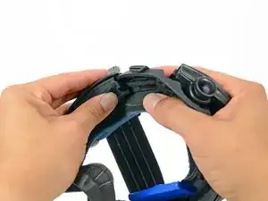
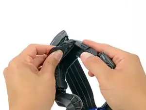
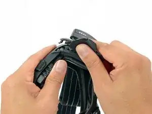
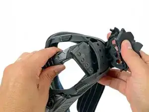
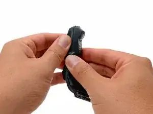
Hold the iON in your hands with your thumbs on the clips next to the middle of the lens.
-
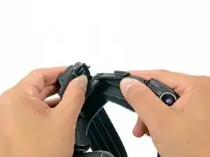
Pull the rubber housing apart to release the first two clips.
-
-
-
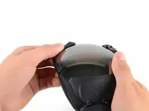
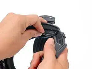
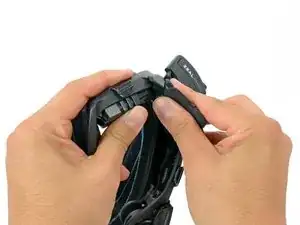
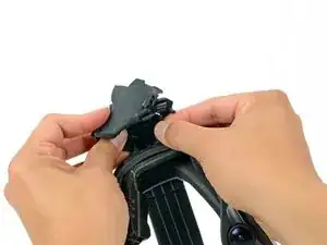
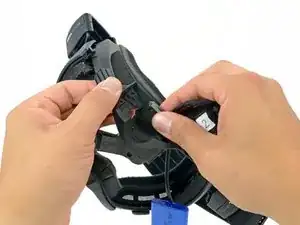
Grab the inside of the plastic nose rest with your thumb and index finger.
-
Rotate the nose rest upwards until you feel that it is free from the lens.
-
-
-
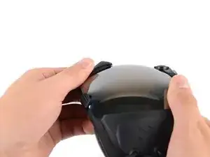
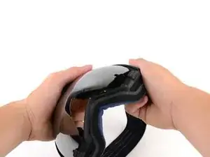
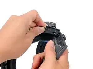
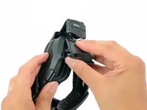
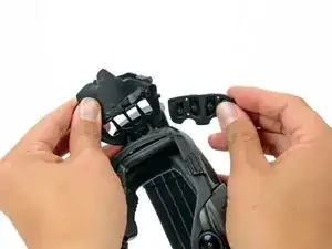
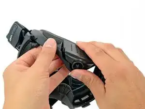
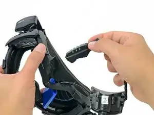
Grab the top of the goggle frame that holds the camera assembly.
-
Rotate the frame outwards until you feel that the clips inside it are free.
-
-
-
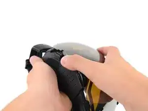
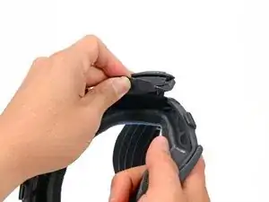
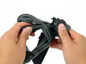
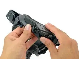
While firmly holding the goggles with the palm of one hand, grab the top right corner of the frame and rotate it away from the lens.
-
-
-
While holding the goggles in one hand, use the other to grab the lens from opposite ends, and rotate it out of the housing and away from any remaining clips.
-
-
-
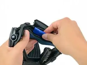
Peel back the rubber battery cover from the inner left side of the frame.
-
While firmly holding the battery cover, pull the bottom of the strap mount cover up and off of the frame
-
-
-
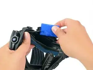
Once the bottom is free, continue pulling to free the top of the strap mount cover from the frame.
-
-
-
Peel the rubber keypad cover up from the inner right side of the frame.
-
While firmly holding the keypad cover, pull the top of the strap mount cover up and off of the frame
-
-
-
Once the bottom is free, continue pulling to free the bottom of the strap mount cover from the frame.
-
-
-
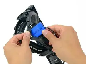
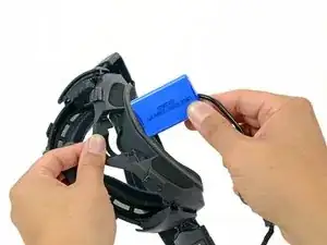
Place one of your hands near the center of the frame with your thumb next to the camera housing.
-
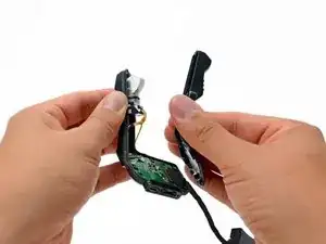
With your other hand, grab the camera housing and pull it up and out of the frame.
-
-
-
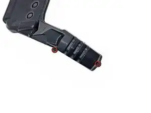
Remove the two 7.5 mm Phillips screws on the front of the viewfinder housing.
-
Remove the four 7.1 mm Phillips screws from the back of the viewfinder housing.
-
-
-
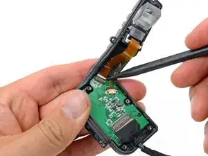
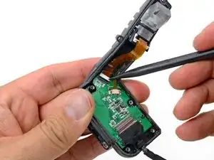
Use the tip of a spudger to flip up the retaining flap on the LCD ribbon cable ZIF connector.
-
-
-
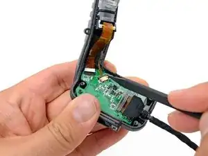
Use the tip of a spudger to push out the retaining clip on the viewfinder backlight ribbon cable ZIF connector.
-
-
-
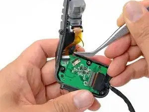
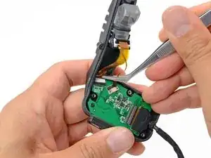
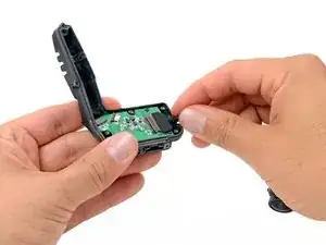
Using your fingers or tweezers, remove the LCD ribbon cable from its connector on the button board.
-
-
-
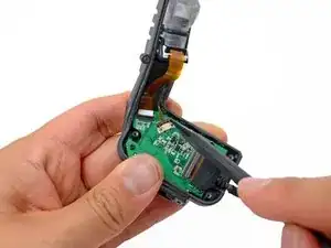
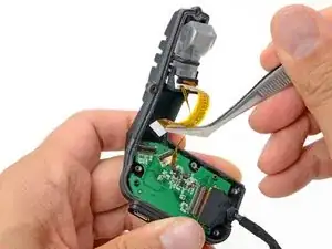
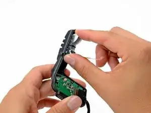
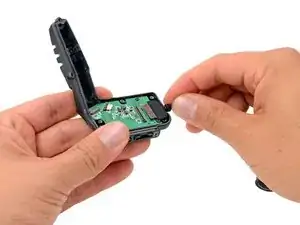
Use the tip of a spudger to flip up the retaining flap on the button board data cable ZIF connector.
-
-
-
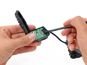
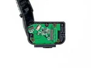
Remove the three 4.5 mm Phillips screws securing the button board to the viewfinder housing.
-


To reassemble your device, follow these instructions in reverse order.