Introduction
The CX260V has a very complicated process in having to take apart all of the external panels in order to access the internal speaker and other internal items.
-
-
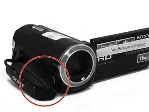
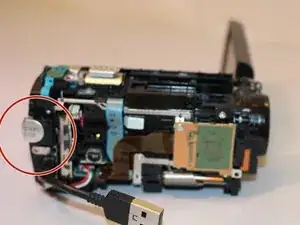
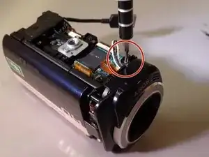
Locate the battery assembly area before removing the 3mm screw and two 5mm screws using a Phillips #00 screwdriver.
-
-
-
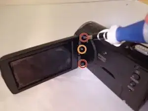
Locate the joint connecting the LCD screen to the camera. Remove the top and bottom 5mm screws before removing the middle 3mm screw.
-
-
-
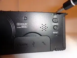
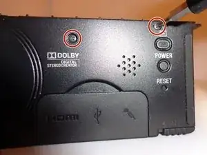
Locate the 5mm screw above the power button and remove it. Locate an additional 5mm screw to the left above the dolby logo and remove it.
-
-
-
Use a plastic opening tool or other piece of thin angled plastic to remove the button’s cover.
-
-
-
Remove the five 5mm screws located on the bottom panel.
-
Locate a panel on the bottom of the camera and remove the five 5mm screws holding it in place. Remove the panel to expose the internal motherboard.
-
-
-
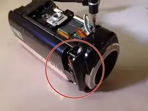
Locate two 5mm screws adjacent to the lens on the opposite side from the LCD screen attachment joint and remove them along with the nearby leather strap.
-
-
-
Remove the panel from the side where the leather strap was located.
-
Rotate the camera back to the other side and remove the 5mm screw to the left of the record button.
-
-
-
Locate the LCD joint cover on the right side of the lens and remove with a spudger or other wide flat-headed object.
-
-
-
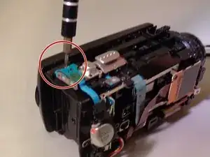
Orient the camera to the side opposite of the recording buttons where the leather strap was. Locate the orange motherboard and remove the three nearby 5mm black screws and 4mm silver screw.
-
-
-
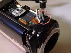
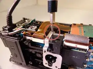
Locate the 5mm screw that is next to both the LCD attachment joint and the camera lens before removing it.
-
-
-
Locate the three 5mm screws holding the lens in place and remove them.
-
Carefully remove the lens by hand or with a spudger.
-
-
-
Locate and remove a 5mm screw at the back of the camera next to the zoom and picture capturing control buttons.
-
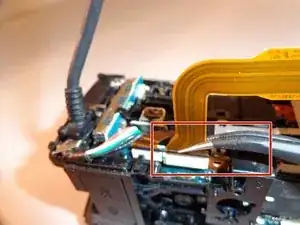
Unplug or carefully set aside the two flat blue wires keeping the buttons connected to the camera.
-
-
-
Locate the silver 5mm screw connected to the tripod mount and remove it to expose the mount assembly.
-
-
-
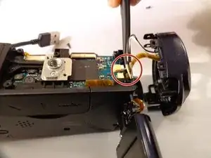
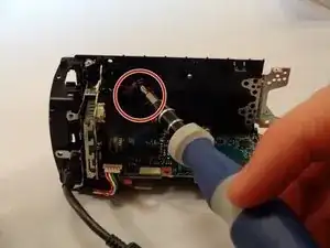
Unplug the wire attached to the orange motherboard.
-
Remove the 5mm silver screw underneath the wire.
-
-
-
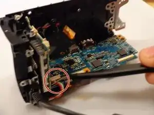
Locate the clip that the other end of the wire that attaches the main internal system from the main frame.
-
Release the clip with tweezers and unplug the cords running through the side panel’s frame, which will allow the rest of the camera to be freely taken apart.
-
-
-
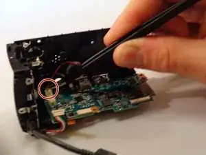
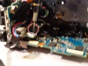
Gently remove the red and black wire connected to the mother board with the tweasers.
-
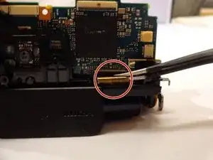
Remove the tri color wires from the mother board. (Has a white connection)
-
Unplug the orange flat wire located at the bottom of the camera.
-
Removes the Internal Speaker
-


To reassemble your device, follow these instructions in reverse order.