Introduction
Use this guide to access the Flash Mechanism so it can be replaced.
-
-
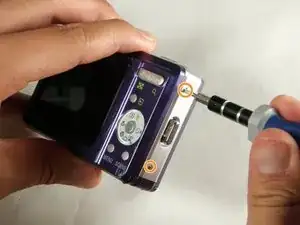
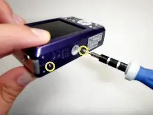
Remove the following six screws using the Phillips #00 screwdriver:
-
Two screws on the left side of the camera.
-
Two screws on the right side of the camera.
-
Two screws on the bottom of the camera.
-
-
-
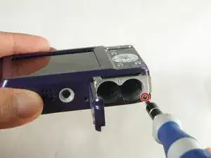
Open the battery slot on the bottom of the camera by sliding the door to the right.
-
Remove the single 4 mm screw on the bottom right using the Phillips #00 screwdriver.
-
-
-
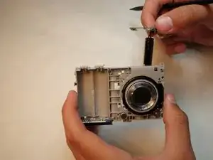
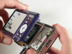
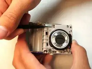
Insert a spudger in the seam at the bottom of the camera.
-
Gently separate the rear case from the front of the camera.
-
-
-
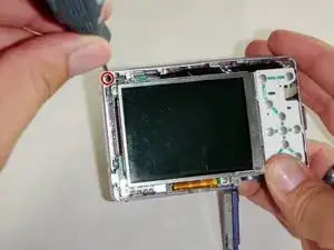
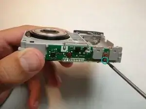
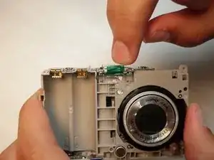
Using the Phillips #00 screwdriver, remove the single screw attached to the front casing in the top left corner. The front case should easily separate.
-
-
-
Using the Phillips #00 screwdriver, remove the screw on the inside of the battery door.
-
Slide the battery door off of the hinge.
-
-
-
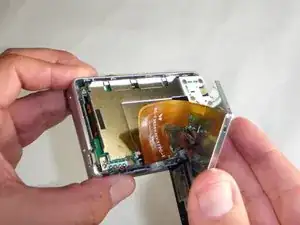
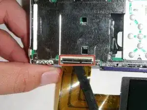
Using the spudger, carefully lift up the LCD screen, making sure to keep the ribbon cable intact.
-
Place the LCD screen on a non-abrasive surface.
-
-
-
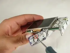
Using the spudger lift the black flap up to release the ribbon cable.
-
The LCD screen will now be completely detached from the camera.
-
-
-
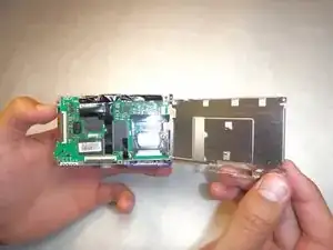
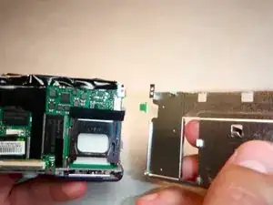
Using the Phillips #00 screwdriver, remove the four screws on the outer edge of the LCD holding plate.
-
-
-
Using your right hand, grab the left side of the LCD holding plate and rotate it to the right.
-
-
-
Using the capacitor discharge tool carefully touch each end of the capacitor discharge tool to the each terminal of the capacitor.
-
Click the link below for instructions on how to make the capacitor discharge tool: Constructing a Capacitor Discharge Tool
-
Keep the wires connected to the capacitor terminals for 2 minutes to completely discharge the capacitor.
-
The camera should be completely safe to handle now.
-
-
-
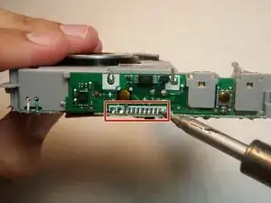
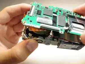
Touch the hot tip of the solding iron to the first solder connecting the flash mechanism to the logic board until the solder melts.
-
Repeat this for the next 10 solders.
-
Verify solders have detached logic board.
-
-
-
Touch the hot soldering iron to the solder in the lower left corner connecting the logic board to the red wire.
-
When the solder has completely melted, gently pull the wire free from the logic board.
-
Repeat for the red, blue, and then black wires.
-
-
-
Touch the soldering iron tip to the solder in the upper right corner connecting the logic board to the battery lead.
-
Pull the battery lead out of the slot in the logic board. This must be done immeadiately after the solder melts.
-
Repeat for the solder to the left.
-
The logic board will now be completely free from the camera.
-
-
-
Insert the battery leads into the slots in the new logic board.
-
Solder both leads to the logic board.
-
-
-
Break the tabs on the camera housing that hold the flash logic board.
-
Lift up on the logic board. The capacitor and the flash bulb will be removed as well.
-


To reassemble your device, follow these instructions in reverse order.