Introduction
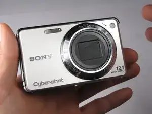
Thorough knowledge of disassembling the camera is necessary for replacing the motherboard.
-
-
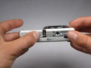
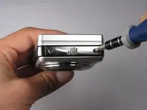
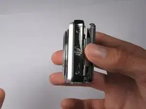
Find the hatch labeled "open" on the left side of the bottom of the camera.
-
Slide the hatch in the direction that the arrow is pointing. The hatch will open outward on its own.
-
-
-
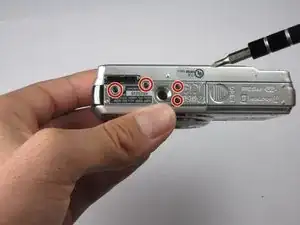
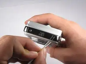
Replace hatch and rotate camera 180 degrees. You should still be looking at the bottom of the camera.
-
Remove the four 2.5mm Phillips #0 screws.
-
-
-
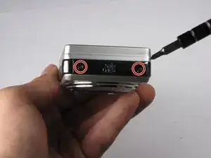
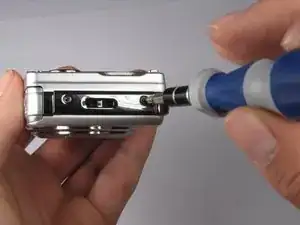
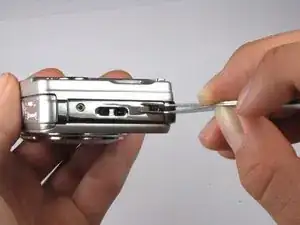
Turn the camera so the left side-panel reading "5x Optical Zoom" faces you.
-
Remove the two 2.5mm Phillips #0 screws.
-
-
-
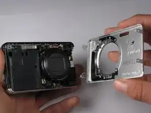
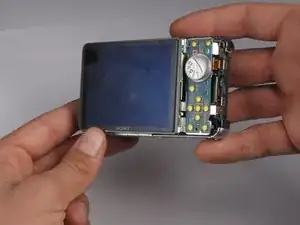
Rotate camera so that the back is facing you.
-
Pull the back casing directly away from the LCD screen.
-
-
-
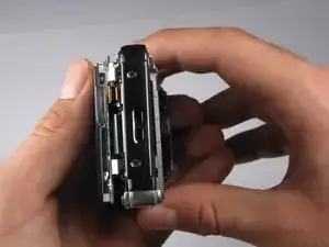
Turn the camera so that the left side is facing you.
-
Pull the left side-panel off of the camera.
-
-
-
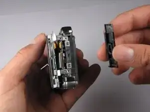
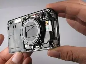
Turn camera so that the front of the camera is facing you.
-
Pull the front casing directly away from the camera.
-
-
-
Turn the camera so that the right side is facing you.
-
Pull the right side-panel away from the rest of the camera.
-
-
-
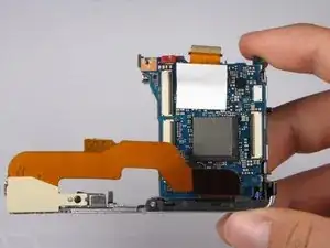
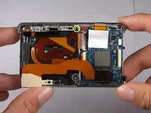
This is what your camera should look like now that you have removed the casing from all sides.
-
-
-
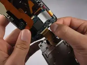
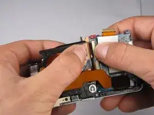
Disconnect the small ribbon-wire by gently pulling on the small ribbon-wire where it connects with the motherboard.
-
-
-
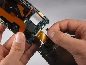
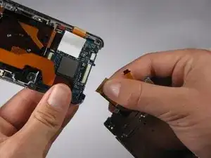
Disconnect the large ribbon-wire by pulling on the large ribbon-wire where it connects to the motherboard.
-
-
-
Turn the camera so the back is facing you.
-
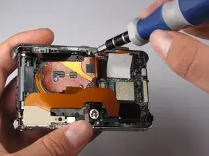
Remove the 2.5mm Philips #0 screw at the top of the camera.
-
-
-
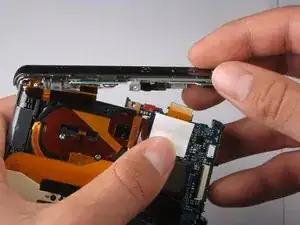
Tilt top casing up and towards you.
-
Carefully remove the right ribbon-wire from the top camera panel by pulling where the wire connects to the top.
-
Carefully remove the left ribbon-wire from the top camera panel by pulling where the wire connects to the top.
-
-
-
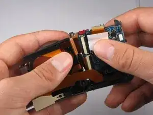
Carefully disconnect the top ribbon-wire from the motherboard by pulling where the wire connects to the motherboard.
-
-
-
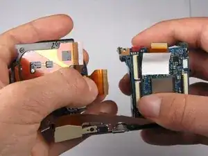
Disconnect the top remaining ribbon-wire by carefully pulling at the base of where the wire connects to the motherboard.
-
-
-
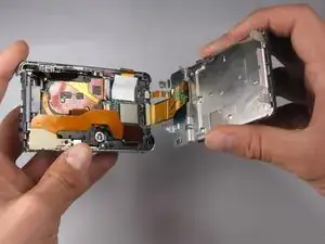
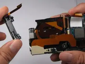
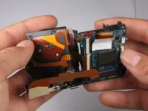
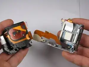
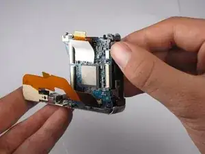
Pull the Lens Assembly away from the motherboard.
-
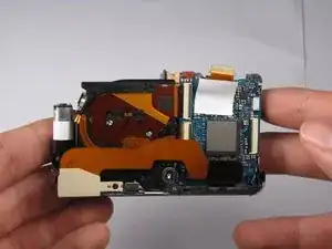
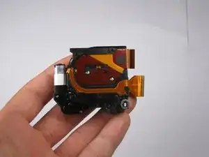
You have now removed the Lens Assembly from the camera.
-
-
-
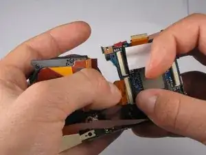
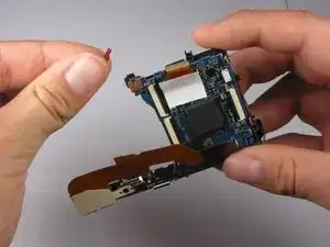
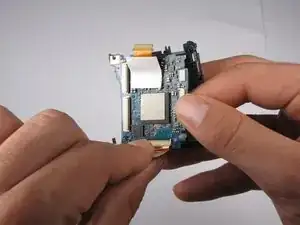
Pull back the small gray clip located on the right side of the camera to release the motherboard from its casing.
-
-
-
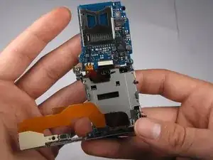
Lift the motherboard from the casing.
-
Carefully remove the large ribbon-wire by pulling the wire where it connects with the motherboard.
-
-
-
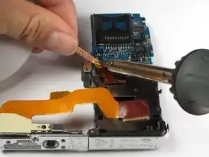
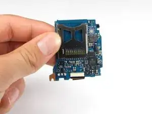
Flip the motherboard up to turn it over.
-
Carefully de-solder the three connectors from the ribbon wire to the motherboard.
-
You have now removed the motherboard.
-


To reassemble your device, follow these instructions in reverse order.