Introduction
-
-
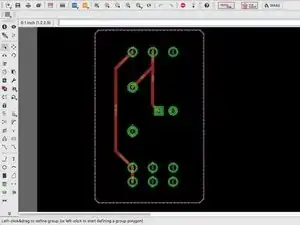
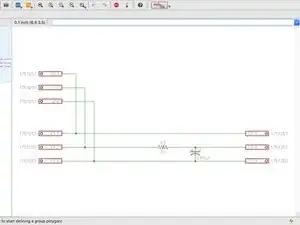
Create the board layout using EAGLE FREE on more information on this step.
-
A video tutorial for using EAGLE for a board layout can be found here.
-
Remove all the labels and export it as a monochrome image (.png).
-
-
-
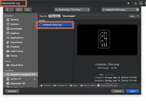
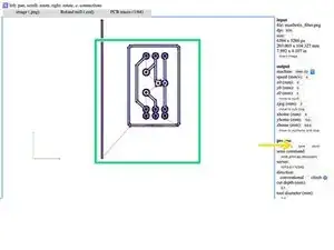
Upload the image to fabmodules.org.
-
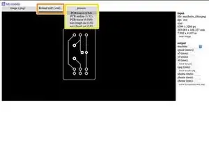
Output format for "Roland mill (.rml)".
-
The process box is how thick you want the cuts. Select "PCP traces (1/64)".
-
-
-
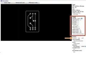
From the output menu, select the following: Machine: SRM-20, X0: 0, Y0: 0, X0: 0. Leave the rest as default.
-
Then select the "calculate" button.
-
Next select the "save" button.
-
The image shows the cut cut patterns. (The red lines are where the machine is picked up and moved to the next spot to cut.)
-
-
-
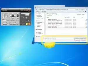
Select the "cut" button which will bring up a new window.
-
Click the "add" button to add a file.
-
Add the file and click "open".
-
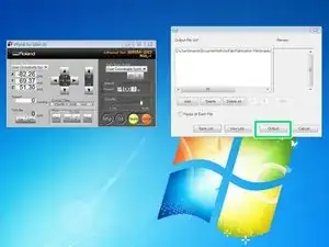
Then select the "output" button.
-
-
-
Set the bit and the material. And set the "home" for xy and for z. See the manual for these instructions.
-
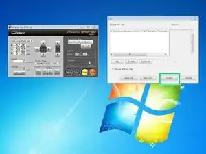
Note: you will see this dialog box when you set the "home". Select "yes".
-
Note: there is a sacrificial board on top to protect the machine.
-
Once everything is ready, select the "output" button. This will begin cutting process.
-