Introduction
Step by step guide to replacing the Main PCB.
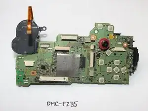
Parts
-
-
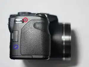
Remove 1 screw (0.4mm) from left side of unit
-
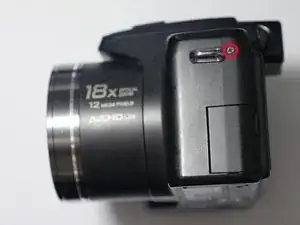
Remove 1 screw (0.4mm) from right side of unit near Strap bar.
-
Remove 1 screw (0.6mm) from right side of unit next to usb door
-
-
-
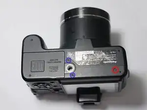
Remove 3 Screws from bottom of unit
-
Remove 2 (0.6mm) screws next to door
-
Remove 1 (0.4mm) screw opposite of door
-
-
-
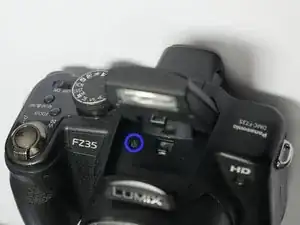
Raise the Pop-Up flash by pushing the flash button.
-
Remove the screw (0.6mm) from underneath the flash assembly.
-
-
-
Lift the cover slightly as shown in picture # 1
-
Tilt the back cover as shown in picture #2. Be careful because the flex cables are still attached.
-
-
-
Flip up LCD cable clamp with a spudger or other tool.
-
Flip up backlite cable clamp with a spudger or other tool
-
Removal of the mic wire is optional. My suggestion is to leave it attached. The mic can get damaged if you pull on the wire.
-
-
-
Remove the 2 screws (0.4mm) that are holding the mic assembly
-
Next step (shown in picture #2) remove the metal mic hold part.
-
Next step (shown in picture #3) use a spudger to pry off the mic. Careful not to damage the wiring.
-
-
-
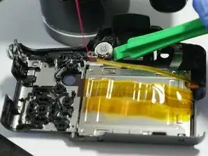
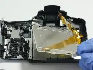
Release the hold clips that hold the LCD retainer in place.
-
Remove the LCD metal retainer plate as shown in picture #2
-
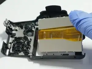
Remove the LCD as shown in picture # 3
-
-
-
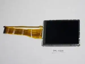
Swap out your old LCD with the new one.
-
If your backlite is ok you can buy only the LCD Display. But it is easier to purchase the LCD with the backlite attached. Replacement LCD Display VYQ5034
-
-
-
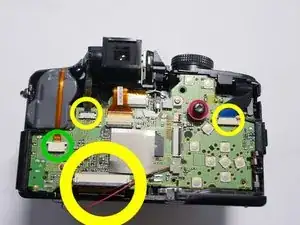
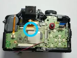
Pull the 3 flex cables out using flat needle nose pliers (it is easier to slide open the black clamps prior to pulling). These are sliding clamps not flip (up) clamps.
-
Pull the single cable from the socket. This is a friction fit socket.
-
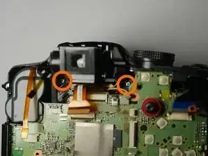
Flip up the Cable clamp (picture #2) using a spudger as shown in the previous pages and release the cable.
-
Flip up the Cable Clamp (picture #3) using a spudger and release the cable.
-
-
-
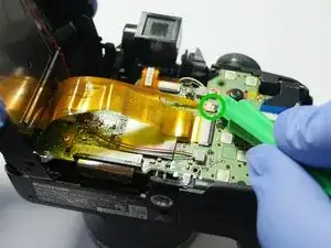
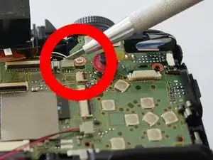
Release the socket. It would be best to use a method that does not require pulling on the wires.
-
One way to release the socket is by carefully inserting a thin wedge between the male and female sockets and carefully pry them apart.
-
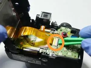
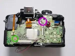
Remove 1 silver screw (0.4mm) next to joy stick.
-
Remove 1 silver blue tip coated (0.4mm) screw bottom left corner.
-
-
-
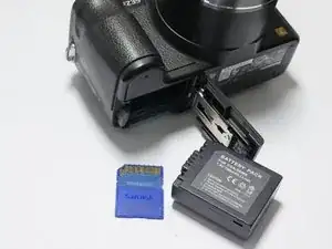
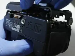
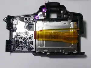
Open battery compartment
-
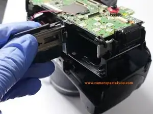
Grab battery door and lift up (do not remove yet) the Main Board and Compartment Part
-
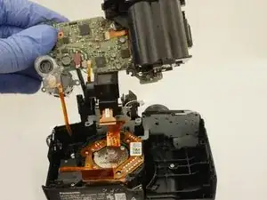
Carefully flip over board and pull up so that the flash assembly rises along with the main board from the camera body. Remove entire assembly from the camera body.
-
-
-
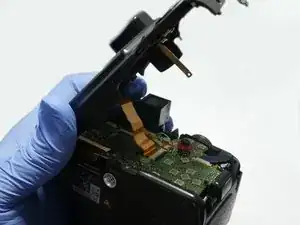
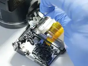
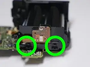
Release the two cables from the main board.
-
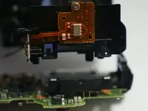
Used spudger to flip up cable clamp and remove flex cable
-
Release the two hold clips and remove battery compartment
-


To reassemble your device, follow these instructions in reverse order.