Introduction
Use this guide if you need to replace your Olympus Stylus Tough-8010 camera's LCD screen.
-
-
Remove the front three screws (3.2mm) using a type T-6 head screwdriver.
-
Take off smaller front cover.
-
Carefully remove larger front cover.
-
-
-
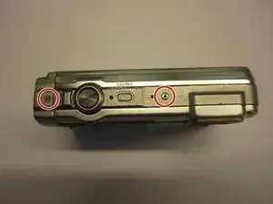
Remove two screws (4.1mm) on the top of the camera using a #000 Phillips head screwdriver.
-
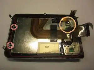
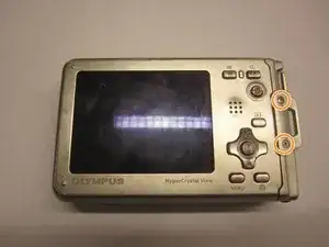
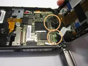
Using a #000 Phillips head screwdriver remove two screws (7.9mm) near the control panel and set aside the metal connector.
-
-
-
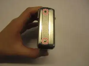
Using a #000 Philips head screwdriver remove the two screws (4.1mm) on the right side of the camera.
-
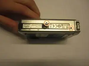
Remove two screws (4.1mm) on the bottom of the camera using a #000 head Phillips screwdriver.
-
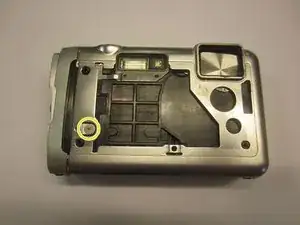
Remove the single screw (3.2mm) on the front of the camera using a #000 Phillips head.
-
-
-
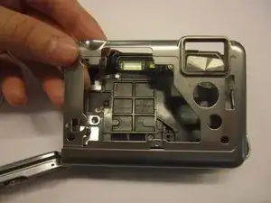
Carefully remove the font panel piece from the rest of the camera.
-
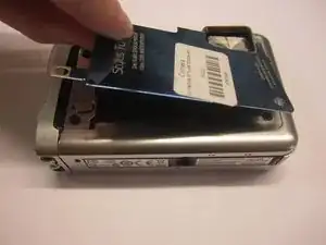
Carefully remove the top/side plastic piece.
-
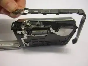
If you haven't already done so, remove the side casing as mentioned in Step 3. It is secured by a single screw near the bottom corner.
-
-
-
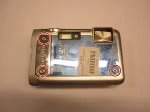
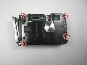
Remove four screws (9.4mm) on the front of the camera using a Phillips #000
-
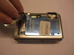
Use the plastic opening tool to release the holding clip.
-
Using tweezers separate the plastic strips from their connectors located on the main circuit board by lifting the small, black flaps on the connectors and pulling on the ribbons.
-
-
-
Remove all the tape and clear rubber material from the components.
-
Remove two screws (4.1mm) using a #000 Phillips head screwdriver on the left side of the lcd component.
-
Using the tweezers disconnect the plastic ribbon from the connector on the control board by lifting the small black flap on the connector and pulling on the ribbon.
-
-
-
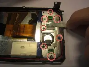
Remove all seven screws (4.1mm) from the metal plates (#000)
-
Carefully lift out the lcd screen component from the camera casing.
-


To reassemble your device, follow these instructions in reverse order.