
Introduction
In this guide, we will give you step-by-step instructions on how to remove the logic board so that it can be replaced or repaired.
Tools
-
-
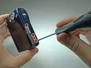
Remove all six 4.3mm silver screws along the perimeter of the camera using the Phillips #00 screwdriver.
-
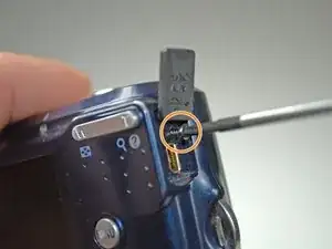
There is one screw hidden under the AV cover that also needs to be removed.
-
-
-
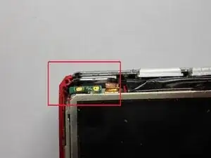
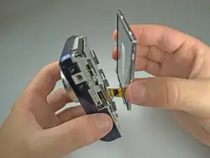
Remove the tape on the right side of the LCD screen.
-
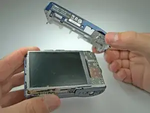
Gently lift the LCD screen from its base.
-
-
-
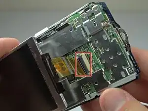
Lift the black latch connecting the LCD ribbon to the motherboard.
-
Gently pull the LCD ribbon out.
-
-
-
Remove the 6 Phillips #00 screws anchoring the LCD base to the motherboard.
-
Remove the LCD base plate.
-
-
-
Lift the black latch connecting the LCD ribbon to the motherboard.
-
Gently pull the lens ribbon out.
-
-
-
Desolder the connection of the motherboard to the lens ribbon using a soldering iron and desoldering wick.
-
-
-
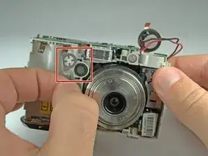
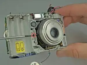
Remove the 3 screws holding the lens to the camera frame.
-
Two 3.8mm black Phillips #00 screws on the sides of the lens.
-
One 4.6mm silver Phillips #00 screw on the bottom of the lens.
-
-
-
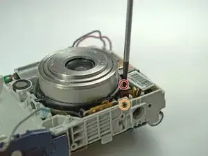
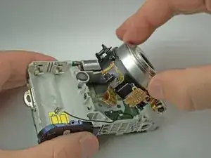
There is a screw behind flash tube holding lens. Remove it, then gently pull the lens out. Be sure that the lens's ribbon clears the motherboard.
-
-
-
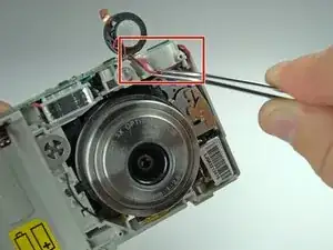
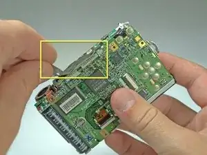
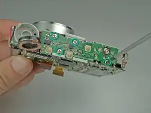
Desolder the joint of the top and back of the logic board using a soldering iron and desoldering wick.
-
-
-
Move the top of the logic board to the side, exposing the top of the frame.
-
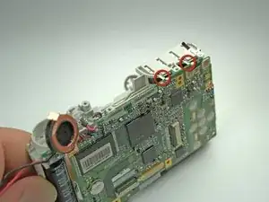
Desolder the two connections on the top right of the logic board using a soldering iron and desolering wick.
-


To reassemble your device, follow these instructions in reverse order.