
Introduction
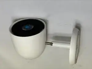
If your Nest Cam IQ motherboard is overheating or shutting down, it requires replacement.
A functional motherboard connects all of your hardware. If you notice a burning smell coming from the motherboard or if the motherboard is off completely, consider changing out your motherboard.
-
-
To soften the adhesive holding the camera together, heat up the edges of the glass lens using a heated iOpener on the device. Alternatively, you can use a heat gun to loosen the adhesive.
-
Leave the Opener on the glass lens for two minutes.
-
-
-
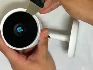
Place a suction cup on the glass lens that you heated up with the iOpener.
-
Press down on the suction cup to create a seal, and pull up with force to create a separation between the glass lens and the body.
-
Pull off the glass lens using the suction cup.
-
-
-
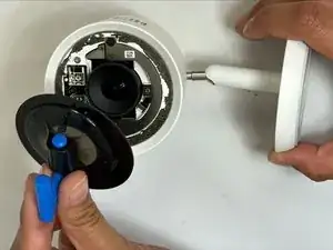
Carefully disconnect the flat black ribbon cable connecting the metal plate to the LED.
-
Remove the metal plate.
-
-
-
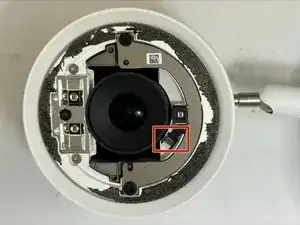
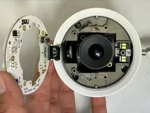
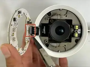
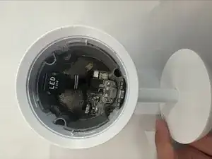
Carefully disconnect the flat black ribbon cable connecting the LED to the motherboard.
-
Remove the LED cover.
-
-
-
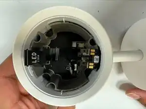
Carefully disconnect the flat black ribbon cable connecting the camera to the motherboard.
-
Remove the camera.
-
-
-
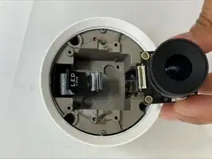
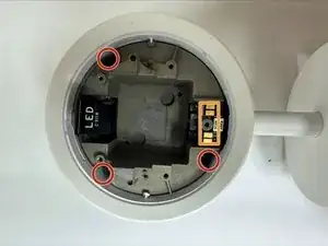
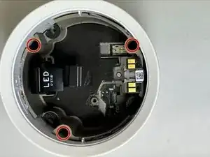
Remove the three 19 mm TR6 Torx screws from the camera holder.
-
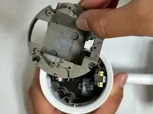
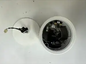
Carefully lift the tab up and away from the camera holder.
-
Remove the camera holder.
-
-
-
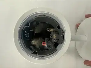
Remove the four 11 mm TR6 Torx screws from the clamp securing the mounting stand.
-
Remove the clamp.
-
Carefully pull away the cables connecting the mounting stand to the body.
-
-
-
Carefully remove the mounting stand.
-
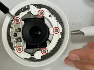
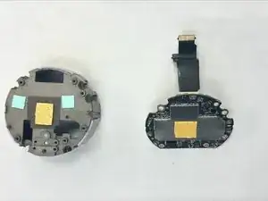
Remove the three 9 mm TR6 Torx connecting the motherboard and speaker to the body.
-
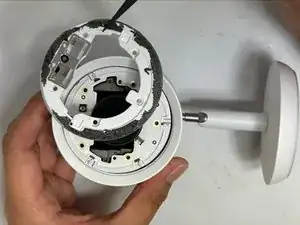
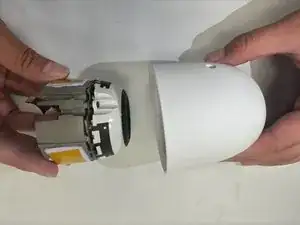
Pull the motherboard and speaker from the body.
-
-
-
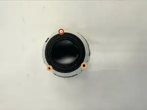
Remove the one 8 mm TR6 Torx screws securing the speaker to the motherboard.
-
Remove the two 4 mm TR6 Torx screws securing the speaker to the motherboard.
-
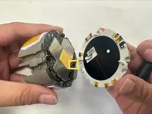
Carefully pull away the speaker.
-
Carefully disconnect the cable connecting the speaker to the motherboard.
-
-
-
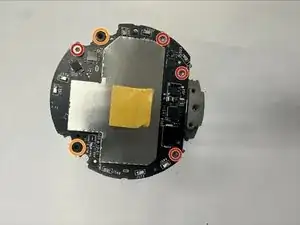
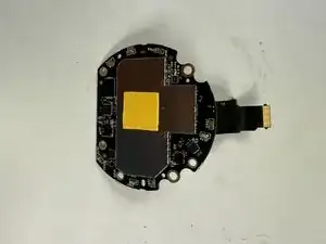
Remove the four 4 mm TR6 Torx screws securing the motherboard.
-
Remove the two 5 mm 3.5 low-head socket cap screws securing the motherboard.
-
Remove the motherboard.
-


To reassemble your device, follow these instructions in reverse order.
