
Introduction
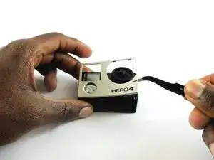
Use this guide to replace a malfunctioning motherboard or expansion port. Because replacing either part requires the same steps, they are both combined into one guide.
-
-
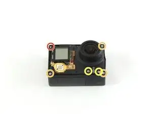
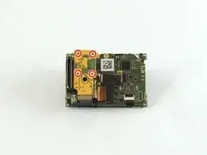
Using a #00 Phillips head screwdriver, remove the following screws:
-
One 4.6 mm screw
-
Three 8.2 mm screws
-
Two 6.1 mm screws
-
-
-
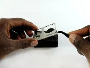
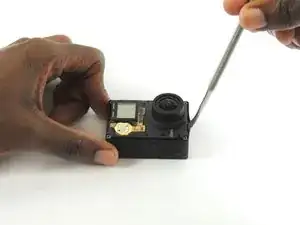
Insert a metal spudger between the back plastic housing and the camera board assembly. Working around the edge to be careful of the inner components, carefully remove the camera.
-
-
-
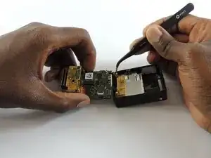
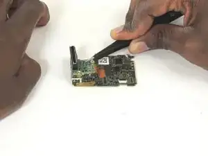
Using tweezers, remove the ribbon strip by pulling on it. This will remove the connection.
-
Push down on the three wires with the metal spudger and the clip will disconnect from the motherboard.
-
-
-
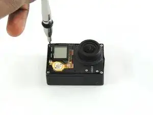
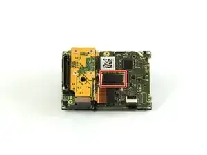
Using a #00 Phillips head screwdriver, remove the four 3.0mm screws holding the camera sensor.
-
-
-
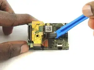
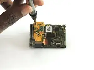
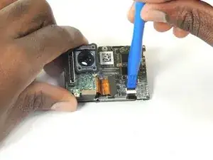
Using #00 phillips head screwdriver, remove the 3.0mm screw.
-
Using the plastic opening tool, unclip the LCD ribbon from the motherboard.
-
-
-
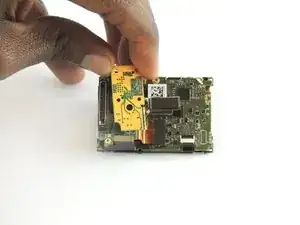
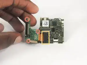
Using #00 phillips head screwdriver, remove the three 4.0mm screws.
-
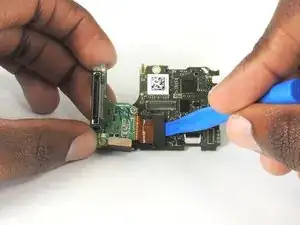
Using plastic opening tool, unclip Expansion Port chip from motherboard
-
-
-
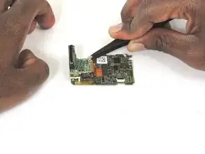
Lift the expansion port chip from the motherboard.
-
It is now possible to replace the expansion port and/or motherboard.
-


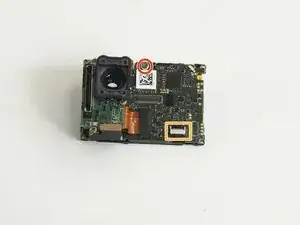


To reassemble your device, follow these instructions in reverse order.
One comment
step 2 is wrong, short screw belongs on the battery door edge... destroyed my new housing... :(