Introduction
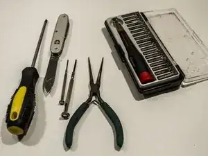
Tools
Parts
-
-
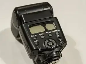
My Speedlight 430EX II was still working perfectly with only the LCD display cracked. The back-light was also still working.
-
Order a genuine replacement part from www.DHcameras.com.
-
Make sure you have a very good set of tools. The screws on this flash are very soft and a none matching driver will strip them.
-
-
-
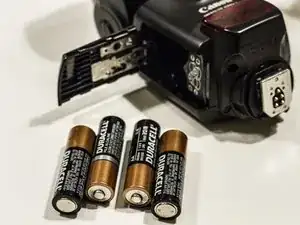
Remove batteries
-
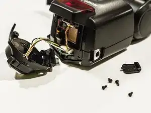
Remove the 4 screws at the bottom of the flash
-
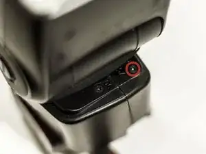
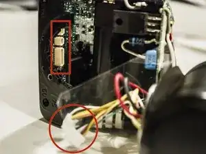
Remove mounting cap on the side of the flash
-
Carefully unplug the socket from the circuit board.
-
-
-
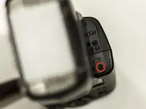
Turn the flash head 90º.
-
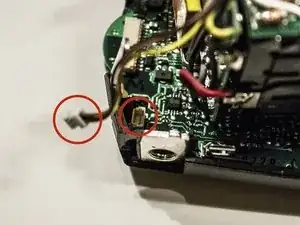
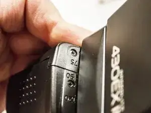
Remove both screws right below the 75 mark. These are the screws holding the smaller back casing in place.
-
-
-
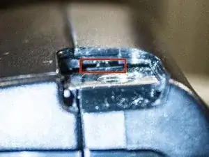
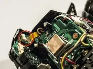
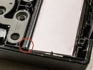
Looking flat into the opening you should see a metal part far in.
-
With a flat driver try to get between the plastic casing and this metal part to pry it out of the locking notch.
-
Image 3 illustrates the metal tab you need to press down for the side to open.
-
One more time: Make sure you are getting between the casing and the metal tab. Inserting and twisting a small screw driver worked for me after a few tries.
-
-
-
Remove front casing with infrared sensor by removing one plug.
-
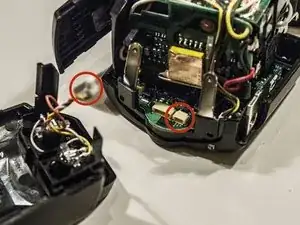
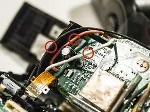
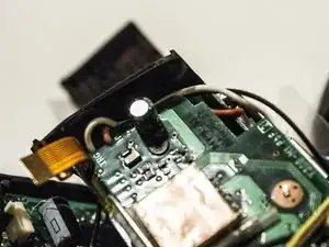
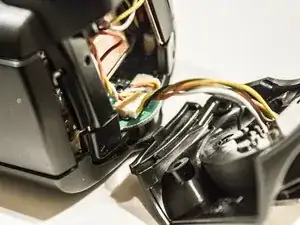
Detach 3 wires going from flash head to circuit board.
-
Remove brown and yellow wire from circuit board connecting the battery case.
-
-
-
Move the 3 wires out from the gap between the casing and circuit board.
-
First: White
-
Second: Orange
-
Third: Black. This is the one we need to free.
-
Now the back casing with circuit board should come lose. Only attached by the black wire.
-
Also pull out the 2 metal mounting plates.
-
-
-
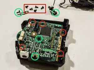
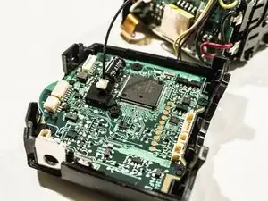
Remove 5 screws holding the circuit board.
-
Remove screw holding metal tab. The screw is different than other 5. Make sure you leave it in the tab.
-
Remove screw holding plastic cap. Keep screw in the cap as it is a different size.
-
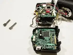
Take the circuit board out of the casing flipping it over.
-
There is a clear plastic plate (red) between the LCD and the circuit board. It might fall out. It is used to distribute the back-light.
-
-
-
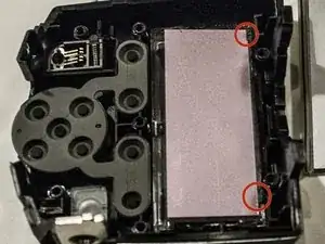
There are 2 tabs (red) the new LCD needs to slide under.
-
Now place the clear plastic plate on top of the new display. MAKE SURE it is in the correct orientation. In the image the BLUE notch is a bit larger than the orange one.
-
Press the edges of the plastic lightly and it will snap into the case.
-
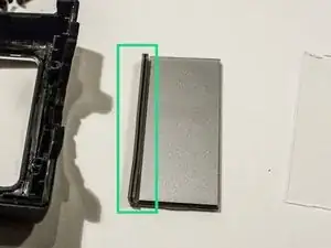
Remove the rubber band gently from the old LCD and place it into the groove (image 3, red). Make sure it is aligned correctly.
-
-
-
Place circuit board back into the casing and attach all screws.
-
If positioned correctly the rubber band will make connection between the new LCD and the board.
-
Push the wires back between the side casing and the circuit board. The order is now reversed: 1st Black, 2nd Orange, 3rd White.
-
Re-attach all connectors onto the circuit board except the flash base.
-
Insert batteries and hold the cap closed with your fingers. It will not snap closed until the casing is back together.
-
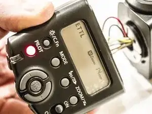
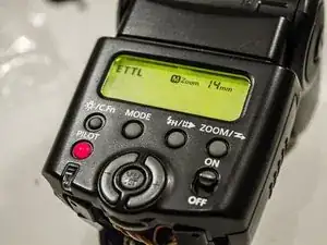
Turn on the flash and check if the LCD works. Push the back-light button (above Pilot) to make sure it works.
-
After the test remove batteries.
-
-
-
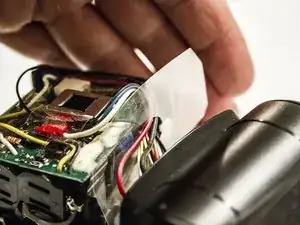
Re-attach the front casing wire for the infrared sensor.
-
Make sure the plastic foil is back in place the correct way around.
-
Put the flash head back between casing halves and snap them together.
-
Attach them with the top screws byt the 75 marks.
-
-
-
Run one more test by inserting batteries. The battery cap should now snap closed.
-
Turn the flash head and make sure all mechanics work including the tilt.
-
Re-attach the wire of the flash foot and put in the 4 screws.
-
Congratulations!!! You just fixed your speed light LCD.
-


To reassemble your device, follow these instructions in reverse order.
21 comments
Whohoo, great! My flash has a new display. THANK YOU!!!
My backlight did not work during the first try in step 9, but it did after putting it all back together. Thanks a lot!
Did you find out what went wrong with step 9?
Many thanks for this superb Step By Step. It worked! Keep up the great work.
cyberK -
You are very welcome. I like to see other very bold people out there fixing stuff!