Introduction
Follow this step by step installation guide for replacing the motherboard on your Canon Powershot SD700 IS camera.
In order to make the process easier please view our more indepth guide on taking off the camera's casing in the LCD replacement guide.
Tools
-
-
To Begin turn off the camera by pressing the power button above the LCD screen. Once that's done we can continue to the next step.
-
-
-
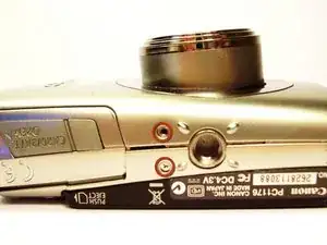
Remove the two, small screws on the bottom of the camera using a Phillip's #00 screwdriver. You will need to save these screws for later. So be sure to set them aside.
-
-
-
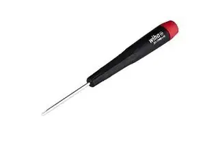
You must use a #00 screwdriver for this step. You can order one online at the ifixit Phillips #00 Screwdriver
-
-
-
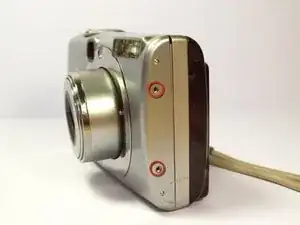
Use a Phillips #00 screwdriver to remove the two, small screws on the right side of the camera. Again be sure to set these aside for later.
-
-
-
Use a Phillips #00 screwdriver to remove the screw on the left of the camera under the A/V out Digital label.
-
-
-
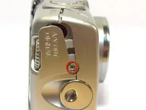
Use a Phillips #00 screwdriver, remove the screw on the bottom of the camera near the battery and memory card slots.
-
-
-
These are the tools necessary for this project.
-
This is a link to buy the spudger Spudger
-
This is a link for the Philips #00 screwdriverPhillips #00 Screwdriver
-
-
-
Once the LCD and Backlight are detached
-
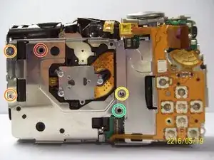
Remove the larger screw marked in red in the picture.
-
as well as the two smaller sized screws orange.
-
remove the small screw marked in yellow.
-
remove the small screw marked in green.
-
-
-
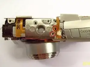
Remove the two screws near the the tri-pod mount that are circled in red, with a Philips head screw driver #00
-
-
-
Remove the screw next to the shutter with a Philip's head screw driver. The screw is on the top side of the camera, where the screwdriver is in.
-
-
-
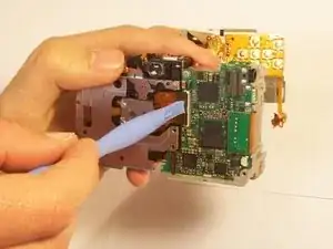
Remove the orange ribbon cable by lifting the ZIF connector attached to the ribbon with a flat head screw driver or spudger. That is boxed in a red line for reference.
-
-
-
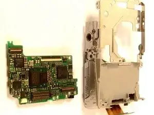
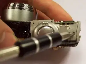
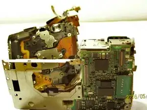
Carefully lift the shutter along with the ribbon connected to it. This will remove the casing around the motherboard.
-
-
-
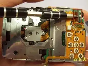
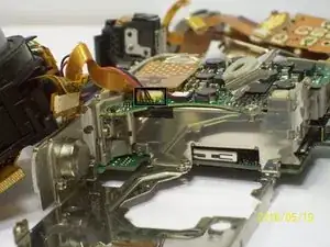
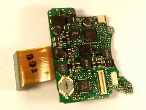
With the motherboard casing detached, remove the short orange ribbon by lifting the ZIF connector with a spudger or other plastic opening tools and slide the ribbon out. Detaching this ribbon will disconnect the side of the camera containing the motherboard from the rest of the camera.
-
-
-
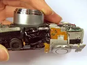
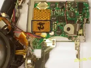
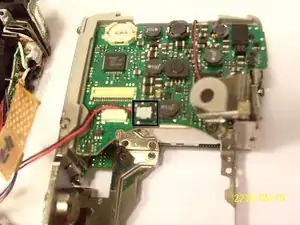
First remove the wires that are attached to the motherboard, as shown by the black box. You can detach them by simply pulling them out.
-
Next you can remove the film by lifting it gently from the motherboard.
-
-
-
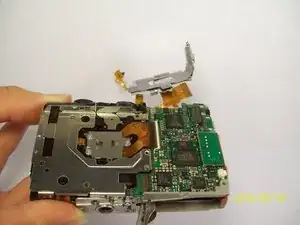
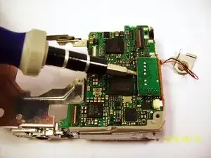
Remove the last wires connected to the motherboard. You can remove it by gently lifting it upwards.
-
-
-
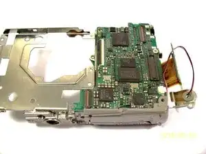
Remove the screw using a philip 00 screwdriver.
-
Once the screw is removed, gently lift the motherboard away from the case.
-
-
-
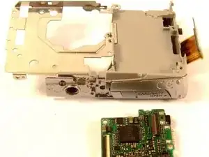
Remove the screw as shown by the red circle.
-
Once the screw is removed, you can remove the board.
-


To reassemble your device, follow these instructions in reverse order.